

COMSATS
UNIVERSITY ISLAMABAD
MICROPROCESSOR SYSTEMS AND INTERFACING
LAB REPORT 1
SUBMITTED TO:
SIR KHIYAM IFTIKHAR
SUBMITTED BY:
JUNAID AHMAD
IBRAR AHMAD
JARRAR MALIK
REGISTRATION NO:
CIIT/FA19-BEE-089/ISB
CIIT/FA19-BEE-083/ISB
CIIT/FA19-BEE-087/ISB
DATE:
26-09-2021
Introduction
to Development Tools and Lab Software’s
Objectives
· Learn to use software development tools such as
Arduino, Integrated Development Environment (IDE) (Atmel Studio, AVR Studio),
avrdudes, and Simulator (Proteus) for the AVR ATmega 328P
microcontroller.
· Learn to program Arduino and ATmega328P
IN LAB
TASKS:
Task 1: Arduino Learning Tutorial
·
In this task I opened the ARDUINO IDE software and open the example code
of blinking led. Then sketch that code on the Arduino uno which have ATmega
328p microprocessor chip on it. Then from one pin of digital port I take an out
put and give it to an LED and ground the led. When the Arduino is powered then
led have started blinking with time delay of 1ms.
The code
for delay is as.
void setup()
{// initialize digital pin LED_BUILTIN as an
output.
pinMode(LED_BUILTIN, OUTPUT);
}
// the loop function runs over and
over again forever
void loop() {
digitalWrite(LED_BUILTIN, HIGH);
// turn the LED on (HIGH is the voltage level)
delay(1000); // wait for a second
digitalWrite(LED_BUILTIN, LOW);
// turn the LED off by making the voltage LOW
delay(1000);
// wait for a second
}
PROCEDURE:
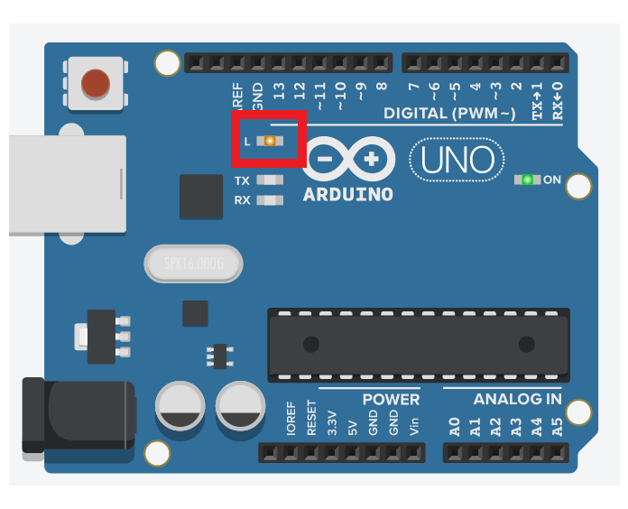
Firstly, Launch Arduino IDE. Then Click on the toolbar menu: File > Examples > Basics > Blink. This will turn an LED on Arduino board on and off with some delay. After which Compile the sketch and upload the code to the Arduino board. Following results were obtained
CODE:


AS WE SEE THE L LED IS ON
Task 2: AVR
Studio Learning Tutorial
PROCEDURE:
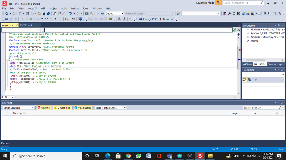
For this task the
code in given in the lab manual. I copied that code and run the code and
generate .hex file for the code and will use it further for simulation and
hardware implementation of program.
/*
*
* Created: 9/21/2021 10:19:52 AM
* Author: MENDUPMIDCODE
*/
#include <avr/io.h>
#define F_CPU 16000000UL
#include <util/delay.h>
int main(void)
{
DDRB=0b11111111;
while(1)
{
PORTB=0b00100000;
_delay_ms(1000);
PORTB=0b00000000;
_delay_ms(1000);
}
}
Task
3: Atmel Studio Learning Tutorial
PROCEDURE:
For this task the
code in given in the lab manual. I copied that code and run the code and
generate .hex file for the code and will use it further for simulation and
hardware implementation of program.
/*
* MAIN.c
*
* Created: 9/21/2021 10:47:41 AM
* Author : MENDUPMINDCODE
*/
#include <avr/io.h>
#define F_CPU 16000000UL
#include <util/delay.h>
int main(void)
{
DDRB=0b11111111;
while(1)
{
PORTB=0b00100000;
_delay_ms(1000);
PORTB=0b00000000;
_delay_ms(1000);
}
}

Task 4(1): Proteus Introductory Learning Tutorial
PROCEDURE:
Open the proteus to simulate microcontroller using proteus. Then
construct the circuit as shown below containing microcontroller ATmega328P from
pick library and animated LED in series with resistor. Following circuit is
obtained, after loading a program in microcontroller through hex file created
in atmel in previous task and then changing frequencies of AT mega 328P to 1Mhz
and clock frequency to 16MH, the circuit was simulated and run and observed
that led started blinking.

Task 4(2):
a. The following code is written
to generate Fibonacci series output at PortB which is given as (0, 1, 2, 3, 5,
8, 13, 21, 34, 55).
b. Build the following code in AVR
Studio or Atmel Studio. Read the error messages, identify, and correct any
syntax errors and rebuild the solution.
c. Use Debugging mode of AVR
Studio or Atmel Studio to debug and correct the code to get the desired output.
In debug mode, open watch window to check the value of the variables.
CORRECT CODE:

POST LAB
TASKS
TASK#1: Blink 5 leds in sequence using Arduino.
CODE:


Results:


Conclusion:
In this lab
we were able to get a brief overview about AVR studio and Proteus. It is
clearly evidential that AVR studio is one of those platforms used to program
microcontrollers. We discussed about the different types of Arduinos and its
working. Although this was a general overview which explained how to create
project, running the program and to upload it on proteus we could have done a
bit more in this lab such as helping us understanding the limitations of this
software and to debug a problem when the software is not working or when the
output files are not being generated.
video tutorial:-
github:-
https://github.com/hiibrarahmad/Lab-01-Introduction-to-Development-Tools-and-Lab-Softwares
Post a Comment